How to infer a network topology with no-cooperative routers, using iTop and Ally
05 Aug 2018
Reading time ~17 minutes
This post is written in collaboration with Andrea Mantovani, for a better reading experience, I suggest to use this pdf
Introduction
In any common industrial network keeping track of its evolution can be not a really trivial task: the changes should be not reported, the current status of the network should not well know or the network admin should be replaced. So an autonomous and automatic system of network scanning could be a very effective tool to help the network maintenance and management.
Starting from this need, the NetTopo project has been built with the goal in mind to supply interesting information from the scanning of a target network. Actually, given a network, NetTopo is able to retrieve its topology, by the implementation of the steps described in iTop[1], and builds a simple inventory actually composed by the network routers along to the IP addresses of their interfaces, guaranteeing an overview to macroscopic level and in detail as well.
To build up a virtual representation of the network target as close as possible to the real one require several steps and some tools in order to refine the raw data and removing possible duplication leading the network size estimation in an overestimation. It’s important to specify that the scanning approach is based on the Traceroute tool, so the network is discovered by running Traceroute commands from a set of network points to obtaining a set of paths which give us a basic definition on how the network nodes are connected with each other (i.e. the topology). However, this approach suffers from two drawbacks which may generate a wrong result:
- Alias: depending on which router’s interface is traversed by the Traceroute, over the set of probed paths the same router appears differently, namely, it appears with the interface’s IP returned by the ICMP packet sent by the router for a packet with time exceeded. This phenomenon is called alias. The topology inferred from the just Traceroute outputs differ from the real one for a number of nodes (might be as more numbers of nodes as the number of interfaces in each router) and end-point connections. For this reason, alias resolution techniques have to be applied to achieve to a correct result.
- Anonymous and Blocking Routers: for security policies internal to the company, to the routers might be denied generating ICMP packets or the routers don’t be allow any ICMP packet traffic or both. This scenarios define what are called anonymous routers and blocking routers: the first ones generating no ICMP packets then negates to the Traceroute to identify their own IP interfaces and so during the probing path they are unrecognizable among each other (in the Traceroute report the anonymous routers results in a “*” symbol); the second ones, the blocking routers, in addition to having the same effects of the anonymous routers, they don’t allow to the ICMP packets to pass through their interfaces and therefore no other routers can be detected by the Traceroute on the other side of the blocking interface.
The resolution of the previous two points are done on two different levels of abstraction of the network exploiting two tools: Ally[2] and iTop[1]. Ally is an alias resolver and will be run over the physical network, instead, iTop starts from the probed path and builds a graph representing the network trying to simplify it as much as it can and filling the gaps left by the anonymous and blocking routers (indeed it is the business logic of the project).
Components
First, to explain how the system works, it’s good to fix the terminology and define the rules of each component of the system that will be involved in the phases of the project. Since we add over the original network a new one, in order to scan the target network properly, let’s define the two network area that composes the final one:
Unknown Network
It is the company network without any overhead, what we want scanning. It’s named so to highlight the fact that we want to know about it as few as possible in order to better generalize the algorithm.
Internal Network
Around to the “Unknown Network”, we build a new network composed of nodes that implement the network scanning, named Monitors, which it sends all the information extracted from the “Unknown Network” to a unique node named Server has the purpose of elaborate them and give an interface to show the inferred network.
The need to add a further network come from the idea to have a common way of work without worry about the state of the “Unknown Network”. In fact, the “Internal Network” provides a safe communication way between Monitors and Server so they can interact independently from “Unknown Network” configurations.
Monitor
As told before the monitor is the component carries out to scan the network and sending the results to the Server. Technically speaking, the monitor is a lightweight computer connected to both the “Unknown Network” and “Internal Network” by two different interface, where a TCP server is running to enable the monitor to speak with the Server, to receive and transmit commands and data. Moreover, the monitor is equipped by the tools Traceroute and Ally in order to detect the path from one network point to another one and to determine potential alias respectively.
The fact that the monitor is bound to the two network by two different interfaces contributes to the “Internal Network” isolation respect to the “Unknown Network”. Since the contact between the two network is done by the monitor itself there’s no way from one to communicate with the other one directly and therefore they are limited to just send the few set of monitor’s commands (in the case of the “Internal Network”) and the response for either a Traceroute request or an Ally one. Indeed, we have the vision of the monitor from two point of views represented as the IPs assigned to the interface attached to the “Internal Network” and that one attached to the “Unknown Network”. By these IPs we can interact with the same monitor both over the “Internal Network”, which it’s useful since no matters how the state of the “Unknown Network” is we have always a valid way to communicate with it, and over the “Unknown Network”, where the real work is done.
To clarify the concept, let’s consider a Traceroute request for two monitors: we want getting the path and its opposite for two monitors which hold their IPs for the “Internal Network”, abbreviated in IntNetIPs, and for the “Unknown Network”, abbreviated in UnkNetIPs. The procedure is just sending a Traceroute request to both through their IPIntNets, containing as Traceroute destination the UnkNetIp of the other monitor. As seen before no matter if the two monitor are truly connected respect the “Unknown Network”, or there are some internal policy negates this, they are by the “Internal Network” without make any changes to the system.
The Monitor actually performs the following operations by receving JSON packets through the TCP Server listener:
Traceroute
Runs the Traceroute tool between the current monitor and those specified inside the request.
- Request:
{ "type": "traceroute", "monitors": [{ "IP": "0.0.0.0" }] }-
type - costant value “traceroute”.
-
monitor - array of objects with the IP attribute set to the UnkNetIp of the target Monitor.
-
- Reply:
{ "type": "string", "from": "string", "to": "string", "hops": [{ "address": "string", "host": "string", "success": "boolean", "ttl": 1 }] }- type - costant value “traceroute_reply”
- from - UnkNetIP of the monitor where the Traceroute has been run.
- to - the UnkNetIP Traceroute target.
- hops - array of the hops reported by the Traceroute. Any hop has the following attribute:
- address - IP address.
- host - Host name.
- success - True if the host replied with a ICMP packet for the expired packet, False otherwise.
- ttl - TTL value when the host has been reached.
Ally
Runs Ally over an IP pair to check if they belong to the same network node.
- Request:
{ type: string, IP1: string, IP2: string }- type - costant value “ally”.
- IP1 - first IP address.
- IP2 - second IP address.
- Reply:
-
{ type: string, IP1: string, IP2: string: equal: bool }- type - costant value “ally_reply”.
- IP1 - first IP address.
- IP2 - second IP address.
- equal - True if it’s the same network node, False otherwise.
Finally we want spending few words talking about the alias resolution since it’s a criucial step of our project and it’s done by the monitor completely. In order to resolve the alias, we apply the Ally tool. This tool uses some heuristic to infers the aliasing and, by their analysis, our tool marks the interfaces as an aliases. The heuristics are:
- When the router is responsive, the alias resolver sends consecutive packets to the first candidates interface IP1 and the second one IP2. If the identification numbers of the replies packets are within 1000, send another packet to the interface that responded first. If the IP ID’s are in order, it’s a match.
- If the returned packets have the same TTL when they reached the monitor, it’s a match. This is true because most aliases will choose the same path to get their response back to the monitor.
- If both responses had the same source IP address, this is a match
- If the response packet sent to IP1 had a source address of IP2, this is a match. This doesn’t imply that that packets have the same source IP address, as a packet sent to IP2 might come back with something different.
- As previous point but with IP1 and IP2 swapped.
Ally is based totally over the ICMP packets so, like the Traceroute, it is defeat by anonymous and blocking router too. In order to work around this issue, alias resoultion is applied by two monitor in opposite location so to reach nodes either inacessible for just one monitor.
Server
The server is the coordinator of the system. It has a static IP, assigned by the Internal Network. When the monitors start, the server is already running and ready to listen for incoming messages. It keeps track of all the monitors connected to the network (as they subscribe themselves to the Server) and ask to the monitors to perform the traceroutes or the alias resolving algorithm. All the information collected from the network will be displayed in a web interface provided by the Server.
System Description
Monitor-Server Protocols
When a monitor joins in the network, it is connected both to server and some router of the Unknown Network. It, first of all, sends a notify packet to the server with its IP interfaces (both the IntNetIp and UnkNetIp). For each monitors already subscribed on the Server, the Server forwards the new Monitor’s UnkNetIp to them and the new Monitor receives the UnkNetIp of all the other ones. Then the monitors, for each IP address received, executes the traceroute and will send the results to the server. This permits to get a pair of traces, from and to the new monitor, in order to combine them.
The server collects all the results and, for each pair, it compares the IP addresses in order to detect cases of aliasing.
For example, given the trace from the monitor A to the monitor B
\[10.10.0.1 \rightarrow 10.10.0.2 \rightarrow 10.10.0.3 \rightarrow 10.10.0.4\]and the trace from the monitor B to the monitor A
\[10.10.1.4 \rightarrow 10.10.1.3 \rightarrow 10.10.1.2 \rightarrow 10.10.1.1\]the server candidates as alias the pairs:
- 10.10.0.1 10.10.1.1
- 10.10.0.2 10.10.1.2
- 10.10.0.3 10.10.1.3
- 10.10.0.4 10.10.1.4
Due the blocking routers, the server cannot invoke Ally by itself. Ally, in fact, uses ICMP packet that may be blocked in some path. So, to resolve the alias, the server sends to the monitors of that path (A and B) an Ally operation for each alias pair candidates.
Of course, some monitors can resolve the alias (i.e. its ICMP packet are not blocked to the candidates), some other cannot. The server, for a positive alias match, merges the IP interfaces under a same symbolic name (e.g. R1, R2, R3). At the end of this phase, the server has two main data structure:
- The traceroute outputs
[ { from: string, to: string, hops: { address: string, host: string, success: boolean, ttl: int } } ] - The Network Data
 {
     monitorName: {
         distance: {
             otherMonitorName : int,
             otherMonitorName1: int,
             ...
         },
         alias: [string]
     }
 }
Server Network Topology Inference
When all the information from the network are collected, the user can start the second phase. This phase runs the iTop algorithm in order to merge all the routers that have not been merged with alias resolving.
In order to infers the correct topology this phase is composed by three subphases.
Phase 1 - Build the graph
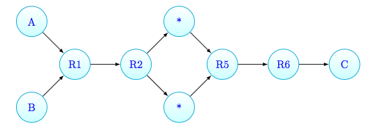
In this phase, all the traceroute outputs are combined together and the first representation of the network is built. Due the blocking and anonymous routers, some same traces can be shown as different ones since, in this phase, we don’t have any available information about these unknown routers. We will refers to these routers as not cooperative, abbreviated in NC.
An example with an anonymous router is given with the following paths, where the trace
\[A \rightarrow R1 \rightarrow R2 \rightarrow * \rightarrow R3 \rightarrow R4 \rightarrow C\]equal to
\[B \rightarrow R1 \rightarrow R2 \rightarrow * \rightarrow R3 \rightarrow R4 \rightarrow C\]except for the starting point, are combined into the following path:
Phase 2 - Detecting Merge Options
Now the server has a graph with a huge number of nodes, that for sure it’s an overestimation of the network. The goal of this phase is analyze the outcome graph of Phase 1 to determine all the merge options for each edge which, in the next phase, will be merged to reduce the size of the graph. The server compare each edge with all other ones and, if any of the following conditions are passed then the two edges are selected for merging.
The condition to pass are:
- Trace preservation: since we suppose that there aren’t any loop in the traces, if two edges appear in the same path they are different and will not be merged.
- Distance preservation: since the server knows the distance between the monitors, if the merging changes the distance between each pairs of the monitors, it is not valid merging
- Compatibility: if the merging of two edges involves the merging of two nodes (its endpoint) and these nodes are not compatible between themselves (see below for compatible definition), the edges cannot be merged
In the case of the blocking routers (given the router after R1 in the path as blocking one), the traceroute output is:
\[A \rightarrow R1 \rightarrow * \rightarrow * \rightarrow * \rightarrow * \rightarrow *\]In this case, the Server searches for the opposite trace and combine the traces adding, between the known routers, some hidden (HID) routers as many as they are required to satisfy the distance declared by the user.
For example, given the opposite trace, with another blocking router:
\[B \rightarrow R4 \rightarrow * \rightarrow * \rightarrow * \rightarrow * \rightarrow *\]the resulting trace that will be added to the graph is:

Node compatibility
Two nodes are compatible for merging according to the table presented in the [1], reported below. We try to gives only the intuition: the compatibility checks if the routers are the same or, in another case, if one is known and other unknown or both of these are unknown. See iTop [1] for more details.

Phase 3 - Merging the edges
In this phase, at each run, an edge with some merge options is selected and, from its merge options, another edge is selected. These two edges are merged. These runs are computed until there is some valid merge option in the remaining edges. At the end of this phase, the Server is ready to show the graph.
The tool
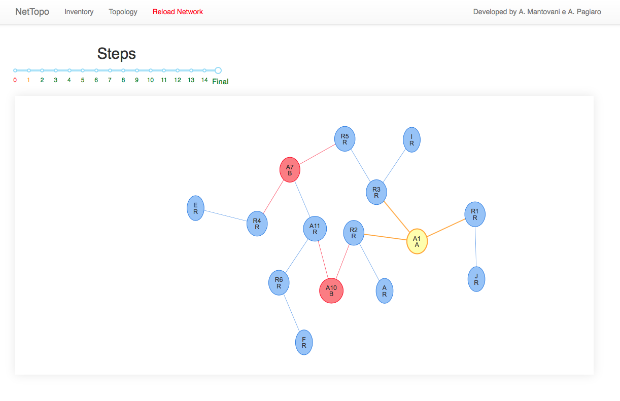
All the information computed by the tool can be retrieved using the Server graphical interfaces. This interface lists all the routers and their IP address interfaces under the Inventory panel. Under the Topology panel is shown the graph computed by the server. In this panel is possible also to see all the runs of phase 3 in order to understand which edges are merged together and understand if some error has occurred.
Case Study
Network A
We have built the following network: 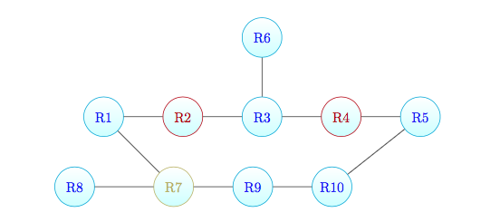 where the red routers (R2 and R4) are blocking ones and the yellow router (R7) is anonymous.
Then, we have attached monitors to the following routers:
- R1
- R6
- R5
- R8
- R9
Our tool finds the correct network topology without any error.
Network B
Another testnet used for validating our tool is the following:
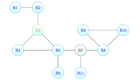
where R7 is blocking router and R3 is anonymous router.
The monitors are attached to the following routers:
- R1
- R4
- R6
- R11
- R9
- R10
In this case, our tool discovers the real topology except for the R8 that its aliases are not resolved, appearing as different routers:
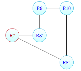
The missing alias is due to our alias resolution strategy. We apply alias resolution when we have the path, for a pair of monitor, in both the directions but in this particular case this strategy fails since R8 doesn’t compare in any returning path. Since R7 is a blocking router, we can consider the network graph as two disconnected (one with R9, R10 and R8, and one with all the other nodes). Now R9 and R10 pass through it toward any node in the other graph but, since there is a direct link between R9 and R10, R8 doesn’t appear in the returning path of R9 and R10 (and viceversa too). So the alias resolution for R8 never starts and the fact that it appears over the traces of R9 and R10, towards the other nodes, doesn’t have any relevance.
For the actual state of the system the solutions are two: don’t limit the alias resolution to the just single path scope but apply it for each pair of encountered IP, but we lead in an expensive task in term of time, or attaching to R8 a new monitor so to make available the returnig path from R8 to R9 and R10. This last solution can be feasible and, for some verses, attractive by its ease implementation but in more complicated scenarios it’s unsafe considering this assumption true a priori. The case study B was to show the limitation of Ally and to suggest how alternative alias resolution techniques should be considered.
Conclusion
This tool is still in developing phase and a lot of new features can be added:
- Subnet Scanning: the monitors can scan their subnet in order to identify their neighbors. Also, running Nmap over these hosts it would be possible discover their running services and reporting them inside the Inventory, growing up the information relative to each system’s component.
- Distance Inference: the monitors can try to infer the distance between other monitors. We have thought some techniques that have to be tested, i.e. try to send packets working on the application level, which they should be not rejected by blocking routers, on a valid port in order to read the TTL remaining at the arriving.
- Multi-level Alias Resolution: Ally alone it’s heavy influenced by the network configurations and may returns some false negative in the case of a congested network. A solution is apply different alias resolution techniques over successive phases in order to not be annoying by the physical world (e.g. alias resolution by graph analysis [3] can be taken into account).
Another problem found is the iTop phases complexity upper bound: \(O(|M|)\) for the phase 1, \(O(|E|^2 \times |V|^3)\) for the phase 2 and \(O(|E|^2 \times |M|)\) for the phase 3 (where M is the set of probed paths for each pair of monitors and E and V are the sets of edges and vertexes of the resulting graph of phase 1). However, the tool resulting from our developing results enough fast to configure, the monitors and the server are simple containers ready to run and they perform all the computation with just the server IP and the monitors’ distance as parameters.
References
[1] Brett Holbert ; Srikar Tati ; Simone Silvestri ; Thomas F. La Porta ; Ananthram Swami Network Topology Inference With Partial Information. IEEE Transactions on Network and Service Management ( Volume: 12, Issue: 3, Sept. 2015 )
[2] Ally tool. https://research.cs.washington.edu/networking/rocketfuel/software/ally-0.1.0.tar.gz
[3] Ken Keys. IP Alias Resolution Techniques. Version 1.1, 2009.